Xia X M, Li H G, Liu S Y, Ran R Q, Cong Y J, Jin Y H, et al. Design and experiment of high-speed straw cleaning unit with double air springs. Int J Agric & Biol Eng, 2024; 17(4): 1–9. DOI: 10.25165/j.ijabe.20241704.8245
Citation:
Xia X M, Li H G, Liu S Y, Ran R Q, Cong Y J, Jin Y H, et al. Design and experiment of high-speed straw cleaning unit with double air springs. Int J Agric & Biol Eng, 2024; 17(4): 1–9. DOI: 10.25165/j.ijabe.20241704.8245
Xia X M, Li H G, Liu S Y, Ran R Q, Cong Y J, Jin Y H, et al. Design and experiment of high-speed straw cleaning unit with double air springs. Int J Agric & Biol Eng, 2024; 17(4): 1–9. DOI: 10.25165/j.ijabe.20241704.8245
Citation:
Xia X M, Li H G, Liu S Y, Ran R Q, Cong Y J, Jin Y H, et al. Design and experiment of high-speed straw cleaning unit with double air springs. Int J Agric & Biol Eng, 2024; 17(4): 1–9. DOI: 10.25165/j.ijabe.20241704.8245
No-tillage planters need to be equipped with row cleaners to remove post-harvest plant residue from the seedbed. The two-disc row cleaners cannot effectively remove the plant residue at high speed because the working depth is unstable, which leads to poor seeding quality of the seeder. A straw cleaning unit with double air springs was designed to achieve better straw cleaning performance at high speeds. The analysis of the mechanical characteristics of the double air spring system showed that it enabled separate adjustment of force and stiffness. A dynamic model of the straw cleaning unit was established, and the effectiveness of the double air spring system with adjustable stiffness in stabilizing the working depth of the row cleaners was analyzed. Field experiments were conducted to evaluate the straw cleaning performance and consistency of downforce against the ground of the straw cleaning unit with double air springs at different high speeds. The results showed that the stiffness of the double air spring system for better straw cleaning performance of the straw cleaning unit was different at different working speed, and the required stiffness increased as the working speed increased; When the working speed was 8-12 km/h, the coefficient of variation of cleaned strip width was 6.9%-12.1%, the straw cleaning rate was 81.6%-92.2% and the root mean square error of downforce was 19.93-28.63 N; the coefficient of variation of cleaned strip width was moderately positively correlated with the root mean square error of downforce, and the cleaned strip width consistency was better when the root mean square error of downforce was lower than 25.00 N.
No-tillage is the main method of conservation tillage, characterized by reducing soil tillage and post-harvest plant residues on the surface[1-3]. No-tillage can effectively reduce wind and water erosion, increase soil organic matter and biological activity[4-6]. No-tillage seeding requires the planter to work in the environment covered with post-harvest plant residues. The opener is easily clogged with a mixture of plant residue and soil from the field, which affects the passing ability of the planter and reduces the seeding efficiency[7]. Plant residues affect the uniformity of the sowing depth which can reduce the quality of the seeds[8]. Plant residues in the seed furrow increase the spread of disease and prevent good interaction between the seeds and soil, which have a negative impact on seed germination and crop yield[9]. Therefore, removing plant residues from the soil surface and avoiding planted seeds being incorporated into these residues is very important to improve the efficiency of no-till planter and the quality of seeding.
Row cleaners have been developed and used as valuable accessories for no-till planter to clean post-harvest plant residues from the seedbed. The performance of row cleaners depended on the amounts of the preceding crop and plant residues left on the soil surface after harvest. The row cleaners installed at the front of the planter can improve the penetration of the opener, avoid clogging the opener with plant residues and improve the seeding performance of no-till planter[10]. The researchers designed different row cleaners depending on the plants to be cultivated or the prevailing soil properties, and improved their straw cleaning capacity by optimizing the structure of the row cleaners[11-14]. Among them, the two-disc row cleaners have been extensively used in no-tillage maize planter, due to its advantages of less disturbance of the soil, good soil moisturizing effect and low working resistance[15,16]. To remove plant residue from the soil strip surface, it is necessary for row cleaner discs to penetrate the soil. Generally, row cleaners penetrate the soil by its own weight. The row cleaner discs are rotated by the pushing force from planter and the soil reaction force, and pushing and throwing the straw to the sides of the seedbed[17]. In addition, the cleaned strip width increases with the increase of the working depth of the row cleaners when the working speed is fixed[18]. The stable working depth of row cleaners guarantees its operational performance and clears a strip of a certain width.
It is difficult for the row cleaners to work at a constant depth due to the poor conditions in no-till fields, such as uneven ground surface and high soil compaction. In the early research, the working depth stability of row cleaners at low speed was improved by adding a coil spring. This control method is simple, but at high working speeds, the working depth stability of the row cleaners is poor due to the spring stiffness and force cannot be adjusted according to the working conditions, and resulting in missed cleaning or inconsistent cleaned strip width[19,20]. In recent years, the depth stability of the row cleaners has been improved by adding an active downforce system. The active downforce systems were developed by replacing mechanical coil springs with hydraulic or pneumatic cylinders or air bags. CASE (USA) developed the Floating Residue Management System to provide active downforce for row cleaners to improve the working depth stability of row cleaners[21]. Wang et al.[22] used a S-type force sensor to monitor the vertical force of row cleaners, and controlled the working depth of row cleaners by using an electric pushing rod. Jia et al.[23] used a force sensor to monitor the downforce of the row cleaners against the ground and applied an air spring to keep the downforce within a set range, which improved the working depth stability of the row cleaners. Current research on the straw clearing performance stability of row cleaners is limited to stabilizing its working depth by applying a controllable force through an active control system.
Air spring has a strong bearing capacity in the vertical direction. Changing the internal pressure of the air spring can change its load force and stiffness[24-26]. Generally, the stiffness and load force of the air spring increase with the increase of its internal air pressure. Therefore, the load force and stiffness cannot be adjusted separately for single air spring. In previous studies, the controllable force of the air spring has been used to improve the performance of of row cleaners or planter[23,27]. In vehicle engineering, the air spring with adjustable stiffness has an active effect in optimizing the dynamic performance of the suspension[28-30]. The double air spring system designed in this study allowed the force and stiffness to be adjusted separately. The double air spring system provided additional downforce to the straw cleaning unit and improved stability of the unit’s working depth at high speeds by adjusting the stiffness.
In this study, a straw cleaning unit with double air springs was designed. The adjustable force and stiffness of double air spring system could improve the working depth stability and the straw cleaning performance of the row cleaners at high speeds. The dynamics model of straw cleaning unit was established and the dynamic analysis of straw cleaning unit was carried out. Field experiments were conducted to evaluate the consistency of cleaned strip width, the straw cleaning rate and the consistency of downforce of straw cleaning unit with different double air spring system stiffness at high working speeds.
2.
Materials and methods
2.1
Structural design
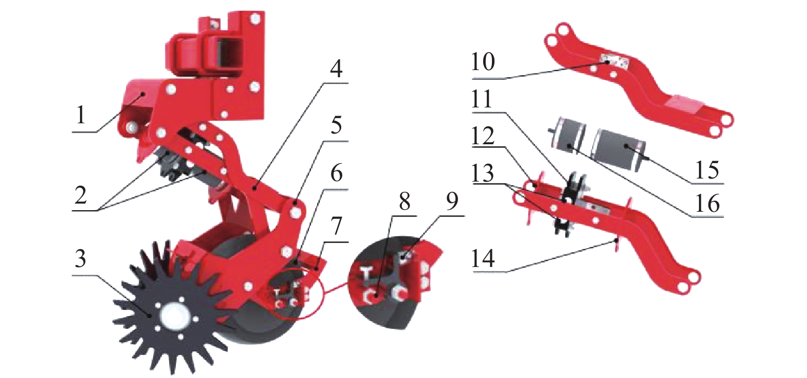
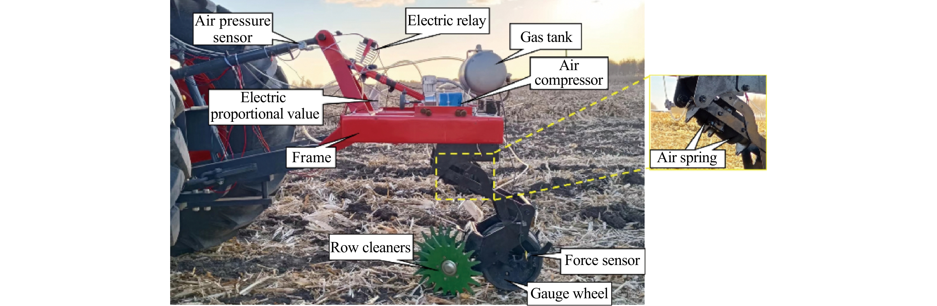
The straw cleaning unit (Figure 1) consists of a frame (1), a double air spring system (2), two-disc row cleaners (3), a parallel four-bar linkage (4), a gauge wheel (6) and two force sensors (9). The row cleaner discs mounted on the fixing frame (5) were staggered front and rear and tilted against each other. The gauge wheel was mounted behind the row cleaners through the gauge wheel fixing frame (7). The working depth of the row cleaners was limited by the gauge wheel and could be adjusted manually. The adjustment range of the working depth of row cleaners was 20-50 mm. As the straw cleaning unit passed over uneven ground, the gauge wheel and the row cleaners moved up and down with the undulations of the ground. Considering the surface fluctuation and field conditions before sowing, the vertical travel of the straw cleaning unit was set to ±120 mm.
Figure
1.
Straw cleaning unit
1. Frame 2. Double air spring system 3. Two-disc row cleaners 4. Parallel four-bar linkage 5. Row cleaner discs fixing frame 6. Gauge wheel 7. Gauge wheel fixing frame 8. Gauge wheel shaft 9. Force sensor 10. Circular shaft 11. Splint 12. Upper base 13. Antifriction bearings 14. Lower base 15. Lower air spring 16. Upper air spring
The air springs were mounted inside the parallel four-bar linkage (Figure 1b). The top end of the lower air spring (15) was consolidated with the lower connecting rod through the lower base (14), and the bottom end was consolidated with the right side of the splint (11); the top end of the upper air spring (16) was consolidated with the lower connecting rod through the upper base (12), and the bottom end was consolidated with the left side of the splint. The splint was connected with the upper connecting rod through the circular shaft (10). Antifriction bearings (13) were installed on both sides of the splint to ensure that air springs always extended and retracted along the connecting rod. The air pressure of the air springs was regulated by an electro-pneumatic proportional valve (ITV2051-212BL, SMC Co., Japan)[27]. The force generated by air springs acted on splint to create a moment that turned the upper connecting rod. This moment provided a pulling force or down force on straw cleaning unit. The force sensors (AR-DN333, Changzhou Allison Technology Co., Ltd, China), mounted on either side of gauge wheel fixing frame, were used to monitor the force of the gauge wheel against the ground by measuring the small deformation of the gauge wheel shaft. The data acquisition card (USB-6210, National Instruments, Inc., USA) recorded real-time forces with a sampling frequency of 200 Hz and stored the data in the laptop.
2.2
Mechanical properties of double air springs
Diaphragm type air springs were used in this study. It is a non-metallic spring consisting of two sealed cover plates and one rubber air bag. The air spring achieves the spring function by compressing the gas inside the air bag. The gas in the air spring is assumed to be an ideal gas. The force Fa generated by the air spring at any moment can be expressed as[31]:
Fa=(P+Pa)Ae
(1)
where, Fa is the force generated by the air spring, N; P is the relative pressure in the air spring, MPa; Pa is atmospheric pressure, MPa; Ae is the effective cross-sectional area of the air spring, m2.
In the process of air spring vibration, the Ae can be expressed as a linear function of the air spring length[32], and the volume of air spring can be expressed as:
V=V0−Aes
(2)
where, V is the volume of the air spring, m3; V0 is the initial volume of the air spring, m3; s is the vertical deformation of air spring, m.
The air spring was stretched or compressed during straw cleaning unit work. Assume that the change in its internal gas is an adiabatic process. According to the ideal gas state equation, the following equation can be obtained:
(P0+Pa)Vγ0=(P+Pa)Vγ
(3)
where, P0 is the initial relative pressure in the air spring, MPa; γ is the adiabatic exponent of gas.
According to Equations (1)-(3), Fa can be expressed as:
Fa=[(P0+Pa)(V0V)γ−Pa]Ae
(4)
The air spring stiffness K can be expressed as:
K=[(P0+Pa)(V0V)γ−Pa]dAeds−γAe(P0+Pa)Vγ0Vγ+1dVds
(5)
The ground surface of the field is continuous fluctuation of small amplitude, so the length of air springs in the straw cleaning unit has little change. There is less variation in the effective area of the diaphragm type air spring[33]. To simplify calculation, assume that the effective area of air spring is Ae0 during movement. Equation (5) can be expressed as:
K=(P0+Pa)γA2e0V0(V0V0−Ae0s)γ+1
(6)
Equation (6) shows that the stiffness of air spring is mainly related to pressure, initial volume, vertical deformation and initial effective area. The initial volume and initial effective area of an air spring are determined. Therefore, the force and stiffness of the air spring can be changed by adjusting the pressure.
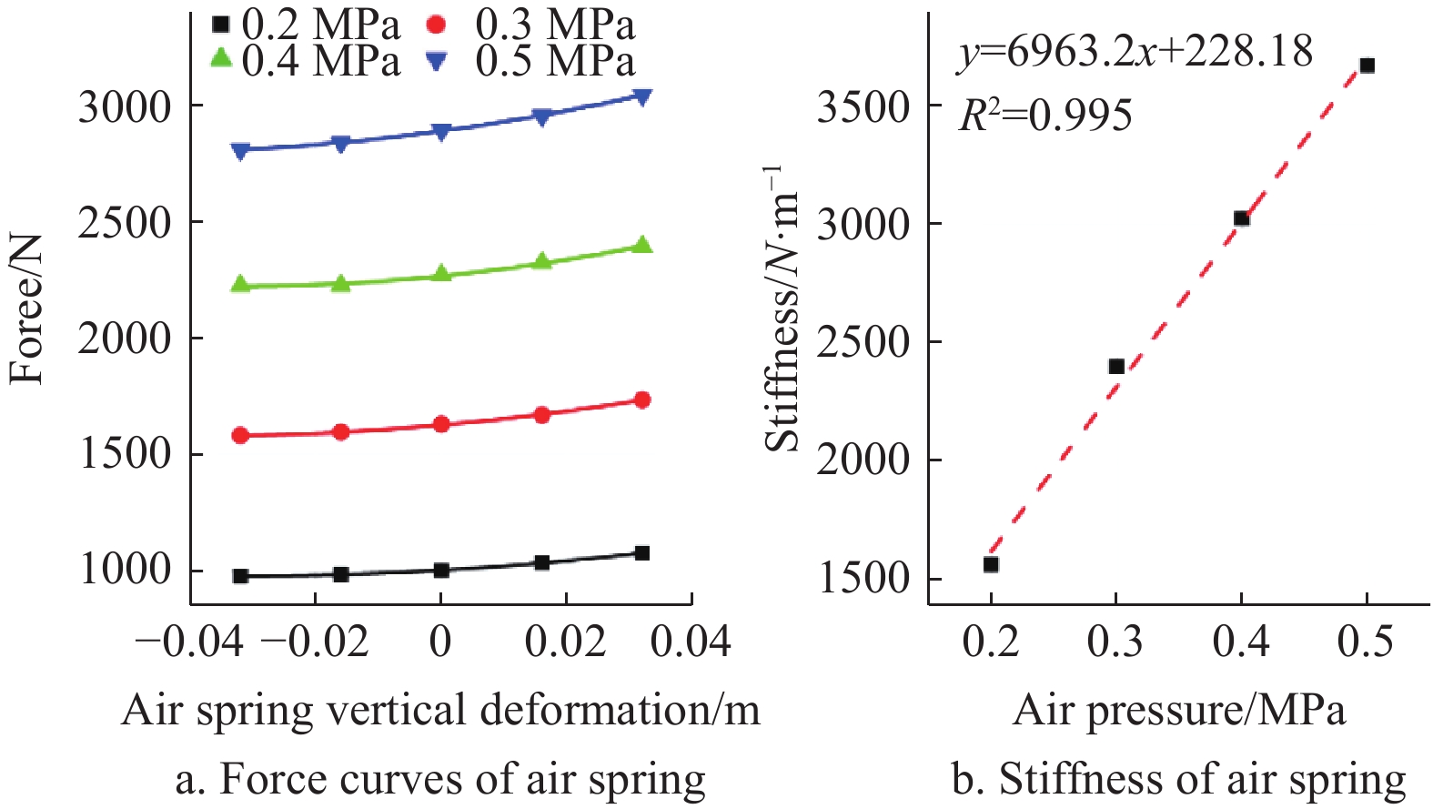
Define the air spring displacement as negative during tension and positive during compression. The isobaric characteristic curve of the air spring is shown in Figure 2a. The slope of the force curve is the stiffness of the air spring. The stiffness of the air spring and the force it produces increase with compression when the pressure is certain. The nonlinearity of the air spring is not obvious when the deformation of the air spring is ±15 mm, so the stiffness of the air spring can be linearized. The relationship between air spring stiffness and air pressure is shown in Figure 2b.
The force F generated by the double air spring system can be expressed as:
F=F1−F2=K1(s0+Δs)−K2(s0−Δs)=(K1−K2)s0+(K1+K2)Δs
(7)
where, F1 is the force generated by lower air spring, N; F2 is the force generated by upper air spring, N; K1 is the equivalent stiffness of lower air spring, N/m; K2 is the equivalent stiffness of upper air spring, N/m; s0 is the initial deformation of air springs, m; Δs is the change in length of the air springs relative to s0, m.
The double spring system stiffness Kt can be expressed as:
Kt=K1+K2
(8)
According to Equations (6), (7) and (8), F does not change when the pressure difference between the two air springs is constant; however, Kt is the sum of the two air springs stiffness and increases as the air springs pressure increases.
2.3
Operation principle and dynamics model of straw cleaning unit
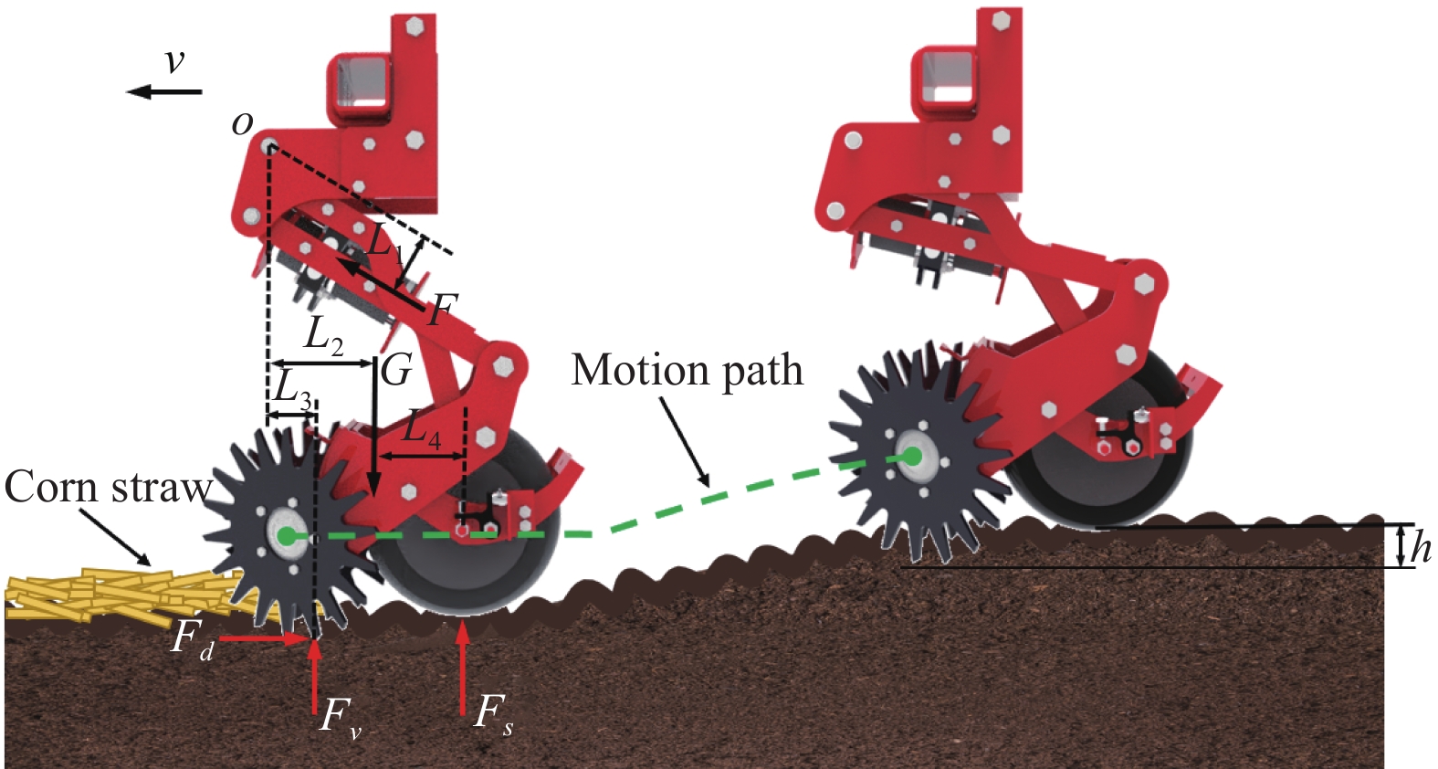
As shown in Figure 3, when the straw cleaning unit was working, the row cleaners overcame the resistance Fv and penetrated the soil relied on the gravity G of the unit and the force F generated by the double spring system. The target working depth h was the height difference between the row cleaners and the gauge wheel. The ground generated the force Fs on gauge wheel when the working depth of the row cleaners reached h. Considering the fact that the horizontal forces have a minor effect on the vertical motion behavior of the straw cleaning unit, the draught forces Fd were neglected when analyzing the vertical motion of the straw cleaning unit[34]. When the straw cleaning unit worked steadily at a constant speed v on a flat surface, the equation of the straw cleaning unit motion can be described as follows:
To ensure a stable working depth of the row cleaners, it was necessary to ensure that the gauge wheel was in close contact with the ground, i.e. that Fs >0. Fv was affected by soil physical and chemical properties and working speed. Under different working conditions, the double spring system provided the downforce for the straw cleaning unit to be able to make Fs >0.
In fact, the surface of the field was uneven. The fluctuation of the ground affected the motion of the straw cleaning unit in vertical direction and caused a change in the row cleaners' working depth. The vertical motion of clear straw monomer was analyzed. To reduce the complexity of the analysis, the assumptions were as follows:
(1) The influence of friction at articulation on the motion of straw cleaning unit is ignored;
(2) The gauge wheel is thought a spring with a stiffness of KL[35];
(3) The stiffness of the mechanical structure of straw cleaning unit is KD;
(4) The resistance generated by the interaction between the row cleaners and the soil is considered as a damping force, and the damping coefficient C is related to the soil rheological characteristics[36];
(5) The double air spring system is considered as a spring with adjustable stiffness of Kt;
(6) The gauge wheel always follows the contour of the ground, and there is no soil subsidence.
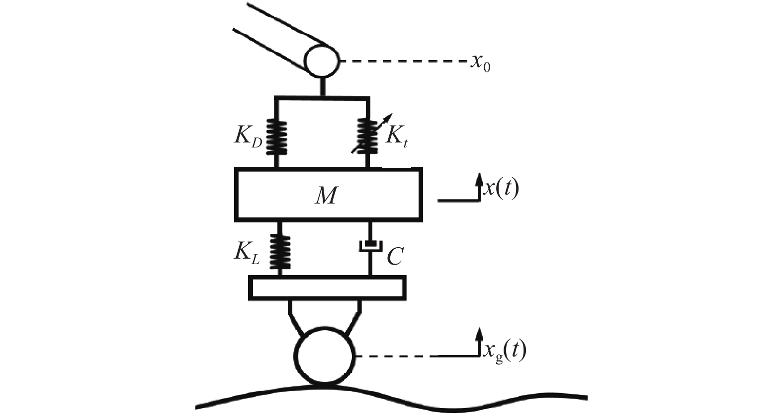
Based on the above assumptions, the dynamic model of straw cleaning unit is shown in Figure 4.
The absolute displacement of the cleaning unit barycenter is x(t). The surface profile is xg(t). The absolute position of the frame x0 remains unchanged. The variation in working depth of the row cleaners h(t) can be described as follows[37]:
h(t)=xg(t)−x(t)
(11)
The motion equation of straw cleaning unit can be described as follows:
m¨x(t)+Ktx(t)+KDx(t)−C˙h(t)−KLh(t)=0
(12)
According to Equations (11) and (12), the following can be obtained:
¨h(t)+2ζ˙h(t)+ω2nh(t)=¨xg(t)+ω22(t)
(13)
ω2n=KL+Kt+KDm,ω22=Kt+KDm,ζ=C2m
(14)
The dynamic model of straw cleaning unit can be approximated as single-degree-of-freedom damped vibration system. Apply the Laplace transform to Equation (15), and the transfer function obtained is as follows:
H(s)=s2+ω22s2+2ζωns+ω2n
(15)
The surface profile of the field can be described as follows[38]:
xg(t)=Asinωt
(16)
ω=2πvTg
(17)
where, A is the height of the surface profile relative to the datum plane, m; v is the working speed of straw cleaning unit, m/s; Tg is the wavelength in the forward direction of the straw cleaning unit, m.
When straw cleaning unit works, the damping of the unit makes the transient vibration of the unit quickly attenuated to zero, and finally only the steady-state vibration is retained. The steady-state vibration of the unit can be described as follows:
As can be seen from Equation (18), the working depth of the row cleaners is influenced by the field environment (soil rheological characteristics, field surface profile), the working speed, and the stiffness and damping of the straw cleaning unit. The variation in working depth h(t) can be reduced by decreasing(ω22−ω2). Equation (17) shows thatωincreases with the increase of surface roughness and working speed. Equation (14) shows thatω2increases with the increase of the double air spring system stiffness. The stability of the working depth can be improved under different working conditions by adjusting the stiffness of double air spring system.
In addition, the dynamic load of the gauge wheel can be expressed as
FQ(t)=KLh(t)+C˙h(t)
(19)
It can be seen from Equation (19) that the dynamic load is affected by the working depth of row cleaners, and can reflect the variation in working depth. In this study, the interaction force between the gauge wheel and the ground was regarded as the downforce of straw cleaning unit to the ground and recorded by force sensors.
2.4
Field experiments
Field experiments were implemented in agricultural field (125°13E, 44°14N) in Nong’an County, Changchun City, Jilin Province, China. The climate was monsoon climate of medium latitudes. The soils in the fields belonged to typical black clay in Northeast China. Field experiments lasted from 24 to 28 October, 2022, with the daily average temperature of 9ºC-16ºC and no significant precipitation. The field was a maize field after mechanical harvest. Straws were crushed and thrown on the surface of the field. The range of straw lengths after crushing was 8-12 cm. The soil compaction was 0.931 MPa, the soil bulk density was 1.16 g/cm3 and the moisture content was 13.6% at soil depth 0-100 mm in the test plots. During the experiment, the straw cleaning unit was towed by a tractor (Figure 5).
Figure
5.
Straw cleaning unit with double air spring system
For all experiments, the working depth of row cleaners was set at 30 mm. Before the experiment, the air pressure difference between the two air springs was adjusted so that the downforce of the straw cleaning unit’s gauge wheel against the ground reached 400 N, which ensured the row cleaner discs penetrated the soil to reach the target depth[23]. Referring to Table 1, there were 3×5 groups of experiments, including 3 levels of working speed and 5 levels of the double air spring system stiffness. The correspondence between the double air spring system stiffness and the air springs pressure is listed in Table 2. The experimental field was divided into 15 plots. Each plot was 200 m long with 20 m start and stop zones. One plot was corresponding to one treatment.
Table
1.
Level settings of the experimental arrangement
(1) The coefficient of variation of cleaned strip width
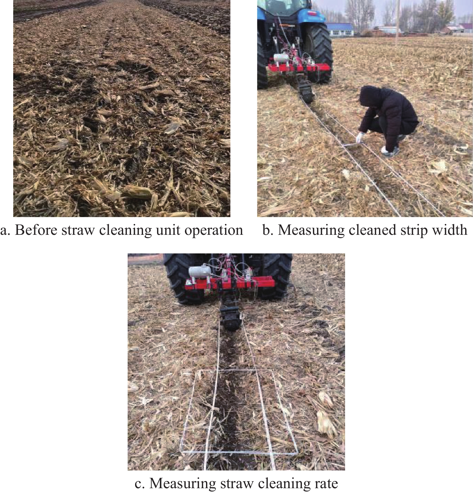
The cleaned strip width varied with the working depth of row cleaners when the working speed of straw cleaning unit was constant[22]. The coefficient of variation of cleaned strip width (WCV) is used to evaluate the consistency of the strip width cleaned by the straw cleaning unit. Larger WCV indicates poorer cleaned strip width consistency. After each group of experiments, 20 sampling points were randomly selected from each plot, and the cleared strip width of the sampling points was measured with steel ruler (Figure 6b). The coefficient of variation of cleaned strip width is expressed as follows:
Figure
6.
Field surface and the measuring method of straw cleaning performance
where, σ is the standard deviation of cleaned strip width, cm; ˉw is the average of cleaned strip width, cm; wi is the ith values of cleaned strip width, cm; n is the number of sampling points.
(2) Straw cleaning rate
The ratio of the straw mass in the strip before and after operation is the straw cleaning rate of straw cleaning unit. The amount of residue on the surface was measured before the experiment. The sampling method is shown in Figure 6c. Ten quadrats (1 m×0.65 m, the row spacing of corn planting in Northeast China is 0.65 m) were randomly selected within each plot and the residues were collected from each quadrat. The residues were oven-dried at 55ºC for 72 h and weighed to determine the dry mass of straw residues in each quadrat.[14]. The average value of the measurement results was taken as the unit mass of the residues before the tests, and was recorded as M. After each experiment, the residues mass of 10 quadrats (1 m×0.65 m) was collected and weighed by the same method. The average value of the results was taken as the unit mass of the residues after the experiments, and was recorded as M1. The straw cleaning rate is expressed as follows:
CR=(1−M1M)×100%
(23)
where, M is the unit mass of the residues before the experiments, kg; M1 is the unit mass of the residues after the experiments, kg.
(3) Consistency of downforce
The responses of the straw cleaning unit to the profile undulations could be expressed by the consistency of straw cleaning unit’s downforce against the ground[39]. The root mean square error (RMSE) of downforce was used to evaluate the consistency of downforce. RMSE increases with the degree of variation in downforce. Larger RMSE indicates poorer ability of the straw cleaning unit to follow the profile undulations. RMSE is expressed as follows:
RMSE=√N∑i=1(Fi−F0)2N
(24)
where, F0 is the target force of the gauge wheel against the ground, N; Fi is the actual force of the gauge wheel against the ground, N; N is the number of data points.
3.
Results and discussion
3.1
Cleaned strip width
The data of 15 groups of cleaned strip width in the field experiment were collected and the coefficient of variation of each group was calculated. The box plots for the cleaned strip width and the line plots for coefficient of variation were produced using Origin 2019b (Figure 7). When the working speed was 8 km/h, the smaller coefficient of variation of cleaned strip width belonged to the stiffness B1 (2893 N∙m-1) and B2 (3938 N∙m-1) with a 25th percentile of 23.1 cm, 23.8 cm, a 75th percentile of 25.5 cm, 26.8 cm, a median of 24.3, 24.9, respectively. Conversely, the stiffness B4 (6027 N∙m-1) and B5 (7071 N∙m-1) indicated the larger coefficient of variation of cleaned strip width. When the working speed was 10 km/h, the smaller coefficient of variation of cleaned strip width belonged to the stiffness B1, B2 and B3 (4982 N∙m-1) with a 25th percentile of 26.4 cm, 28.6 cm, 27.5 cm, a 75th percentile of 30.3 cm, 31.7 cm, 30.9 cm, a median of 28.0 cm, 30.7 cm, 29.1 cm, respectively. Conversely, the stiffness B4 and B5 indicated the larger coefficient of variation of cleaned strip width. When the working speed was 12 km/h, the smaller coefficient of variation of cleaned strip width belonged to the stiffness B3 and B4 with a 25th percentile of 29.5 cm, 29.4 cm, a 75th percentile of 33.7 cm, 36.6 cm, a median of 31.3 cm, 32.2 cm, respectively. Conversely, the stiffness B1, B2 and B5 indicated the larger coefficient of variation of cleaned strip width.
Figure
7.
Cleaned strip width and the coefficient of variation
The experimental results showed that the range of double air spring system stiffness that minimizes the coefficient of variation of cleaned strip width at different speeds was different. When the stiffness was too high, straw cleaning unit was easy to impact the ground, which led to a sharp increase in cleaned strip width. When the stiffness was insufficient, straw cleaning unit was easy to bounce, which led to a sharp reduction in cleaned strip width. When the working speed was 8-12 km/h, the double air spring system stiffness corresponding to the smaller WCV increased with the increase of the working speed. The adverse effect of ground shape on straw cleaning unit increased with the increase of working speed. Increasing the double air spring system stiffness improved the stability of the working depth and cleaned strip width. In addition, the cleaned strip width increased with the increase of working speed, and Kristina et al. have established that the working speed significantly influences the cleaned strip width[18]. The rotation speed of row cleaners increased as the working speed increased, which increased the interaction force between the row cleaner discs and the straw and the straw throwing distance.
3.2
Straw cleaning rate
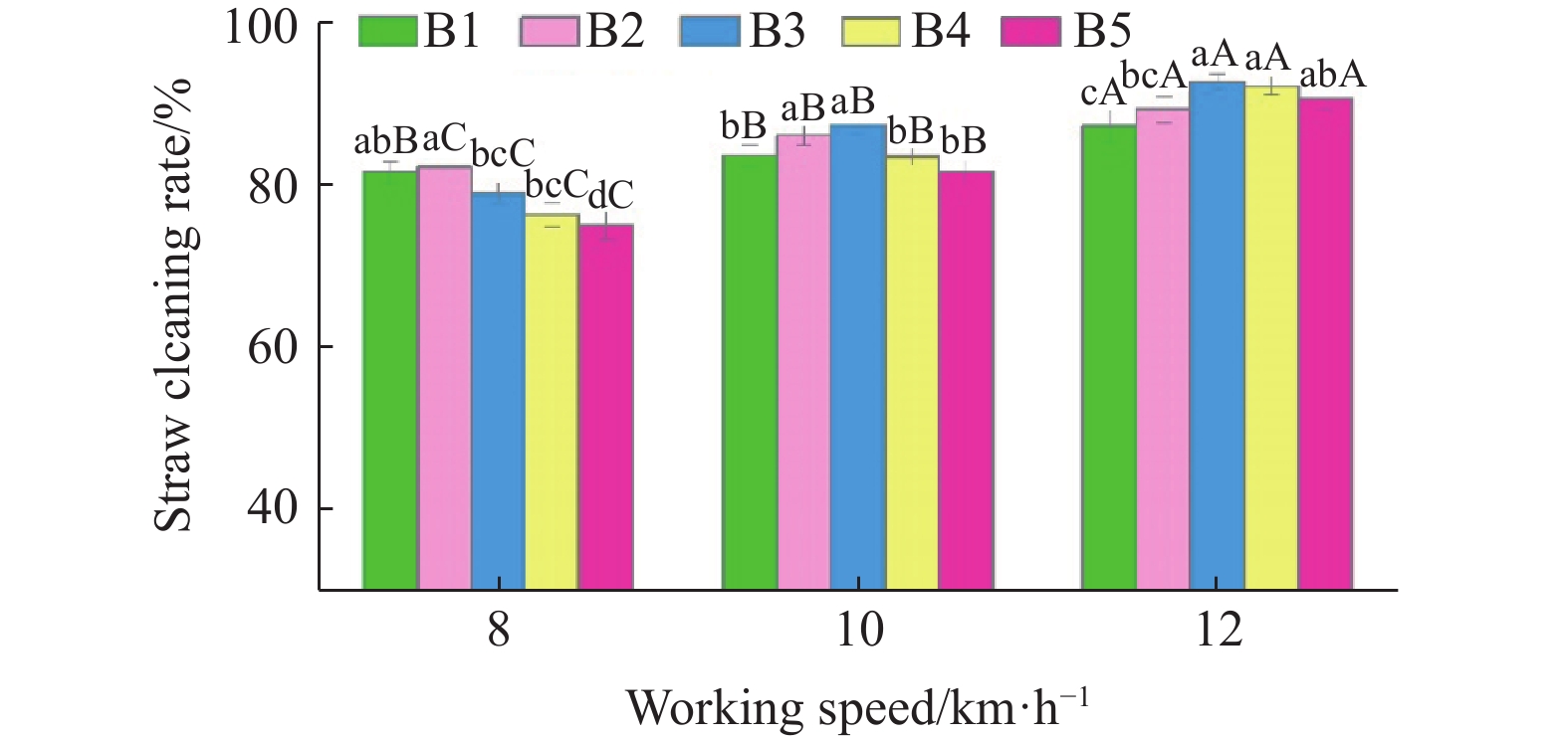
The effect of working speed and double air spring system stiffness on the straw cleaning rate is shown in Figure 8. The experimental results showed that the range of double air spring system stiffness that maximizes straw cleaning rate at different speeds was different. At the same speed, there was a range of stiffness that made the straw cleaning rate better. When the working speed was 8 km/h, the straw cleaning rate of the stiffness B1 and B2 was no less than 81.6% and significantly better than the stiffness B3, B4 and B5. When the working speed was 10 km/h, the straw cleaning rate of the stiffness B2 and B3 was no less than 86.1% and significantly better than the stiffness B1, B4, and B5. When the working speed was 12 km/h, the straw cleaning rate of the stiffness B3 and B4 was no less than 92.2% and significantly better than the stiffness B1 and B2.
Figure
8.
Effect of working speed and double air spring system stiffness on the straw cleaning rate
Note: At the same working speed, columns labeled with same lowercase letters are not significantly different at 95% confidence interval. At the same stiffness, columns labeled with same capital letters are not significantly different at 95% confidence interval.
Straw cleaning rate represents the straw mass in the quadrat after straw cleaning unit operation. When the working speed was 8-12 km/h, the working speed significantly affected the straw cleaning rate. The cleaned strip width increased as the working speed increased, which made the straw mass in the quadrat decreased and the straw cleaning rate increased. The increase of the coefficient of variation of cleaned strip width led to the decrease of straw cleaning rate at the same speed. In conclusion, the straw cleaning rate of the straw cleaning unit was better at high working speeds when the cleaned strip width was stable.
When the working speed was 8 km/h and the double air spring system stiffness was lower (B1, B2), the straw cleaning unit performed better in straw cleaning (CR≥81.6% and WCV≤6.9%). At a working speed of 10 km/h, the straw cleaning unit had a better straw clearing performance (CR≥86.1% WCV≤9.1%) with double air spring system stiffnesses of B2 and B3. When the working speed was 12 km/h, the straw cleaning performance of the straw cleaning unit was better (CR≥92.2%, WCV≤12.1%) at higher double air spring system stiffness (B3, B4). In conclusion, different stiffness ranges of the double air spring system were required at different high speeds to optimize the straw cleaning performance of the straw cleaning unit, and the optimal stiffness range increased with the increase of working speed.
3.3
Consistency of downforce
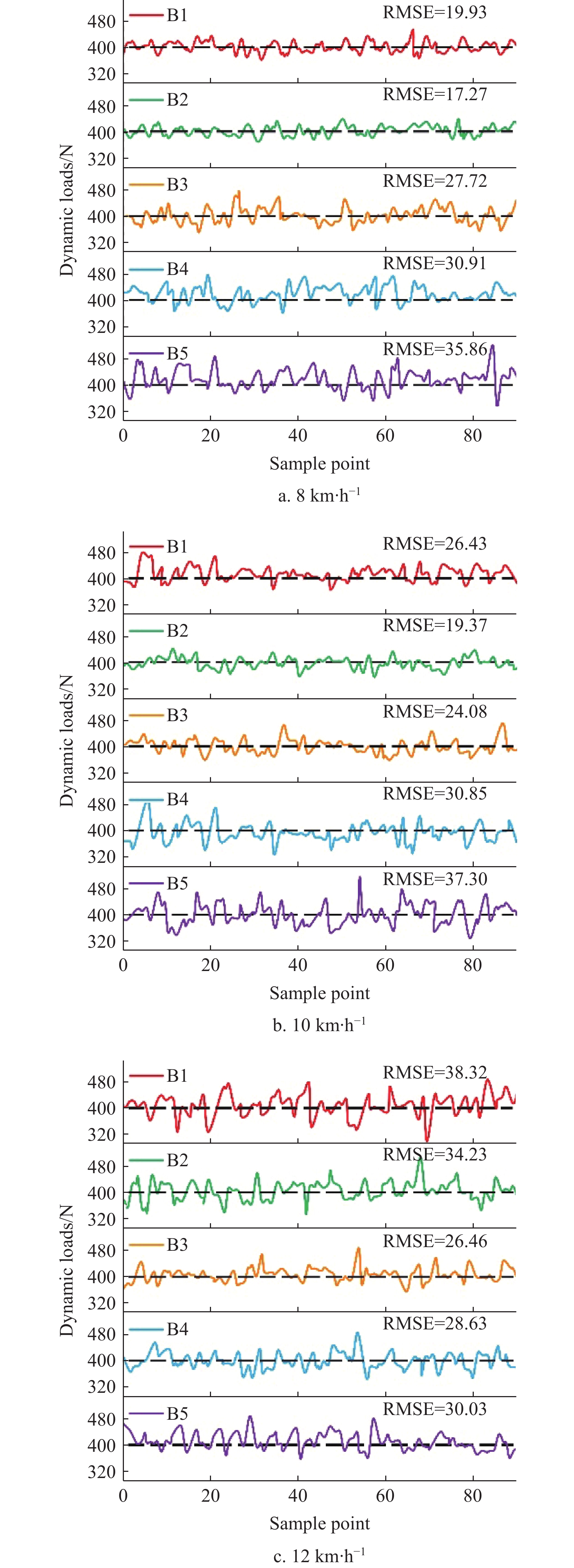
The downforces of the straw cleaning unit are shown in Figure 9. When the working speed was 8 km/h, the dynamic performance of the stiffness B1 and B2 was better and the worst (RMSE=35.86 N) when the stiffness was B5. At lower working speeds, the higher stiffness of the double air spring system reduced the sensitivity of the straw cleaning unit to surface fluctuations, and therefore the unit was prone to impact the ground, which led to a sharp increase in downforce and RMSE. When the working speed was 10 km/h, the best downforce consistency of the straw cleaning unit (RMSE=19.37 N) was achieved with a double air spring system stiffness B3; however, it was the worst with stiffness B5 (RMSE=37.30 N). When the working speed was 12 km/h, the best downforce consistency of the straw cleaning unit (RMSE=26.46 N) was achieved with stiffness B3; however, it was the worst with stiffness B1 (RMSE=38.32 N). The effect of surface fluctuation and soil resistance on the downforce consistency of straw cleaning unit increased with increasing working speed. When the stiffness was insufficient, straw cleaning unit was easy to bounce, which led to a sharp reduction in downforce and a sharp increase in RMSE.
Figure
9.
Downforce recordings of straw cleaning unit
3.4
The effect of downforce consistency on the coefficient of variation of cleaned strip width
The relationship between the coefficient of variation of cleaned strip width and the root mean square error of downforce is shown in Figure 10. The correlation between two datasets can be expressed by Pearson correlation coefficient (r). The closer the absolute value of r is to 1 the stronger the correlation between the two variables, and the closer it is to 0 the weaker it is[40]. The coefficient of variation of cleaned strip width was significantly correlated with the root mean square error of downforce (P<0.01), and both were positively correlated. The coefficient of variation of cleaned strip width and the root mean square error of downforce were moderately related (r=0.69).
Figure
10.
Relationship between the coefficient of variation of cleaned strip width and the root mean square error of downforce
The correlation analysis showed that downforce consistency could reflect the stability of straw cleaning performance. Reducing the root mean square error of downforce could improve the straw cleaning performance of straw cleaning unit. When the root mean square error of downforce was less than 25 N, the width consistency was better (WCV<10%).
4.
Conclusions
This study designed a high-speed straw cleaning unit with double air springs. The double air spring system, with separately adjustable force and stiffness, was used to improve the stability of the straw cleaning unit working depth, thereby improving the straw cleaning performance.
(1) A dynamic model of the straw cleaning unit was developed. The dynamic model of straw cleaning unit can be approximated as single-degree-of-freedom damped vibration system. The dynamic analysis showed that adjusting the stiffness of the double air spring system could improve the working depth stability of straw cleaning unit.
(2) The results of field experiments showed that the adjustable stiffness of the double air spring system facilitated the straw cleaning performance of the row cleaning unit, and the stiffness of the double air spring system, which enabled better straw cleaning performance, increased with increasing working speed. When the working speed was 8-12 km/h, the coefficient of variation of cleaned strip width was 6.9%-12.1%, the straw cleaning rate was 81.6%-92.2% and the root mean square error of downforce was 19.93-28.63 N.
(3) The coefficient of variation of cleaned strip width and the root mean square error of downforce were moderately positively correlated. Reducing the root mean square error of downforce could improve the straw cleaning performance of straw cleaning unit. The coefficient of variation of cleaned strip width was less than 10% when the root mean square error of downforce was lower than 25.00 N.
Since the straw cleaning unit’s downforce consistency can reflect the straw cleaning performance, future research should be focused on developing different control techniques, such as real-time adaptive PID and fuzzy hybrid controller, to optimize straw cleaning performance by stabilizing downforce. Further field experiments are required to evaluate the effect of straw cleaning unit on the working performance of the planter.
Acknowledgements
This work was financially supported by National Key Research and Development Program of China (Grant No. 2023YFD1500404) and Jilin Science and Technology Development Plan (Grant No. 20220508113RC).
Blanco-Canqui H, Ruis S J. No-tillage and soil physical environment. Geoderma, 2018; 326: 164–200. DOI: 10.1016/j.geoderma.2018.03.011
[2]
Wang Q J, Lu C Y, Li H W, Jin H, Khokan K S, Rabi G R, et al. The effects of no-tillage with subsoiling on soil properties and maize yield: 12-Year experiment on alkaline soils of Northeast China. Soil and Tillage Research, 2014; 137: 43–49. DOI: 10.1016/j.still.2013.11.006
[3]
Arshad M A, Schnitzer M, Angers D A, Ripmeester J A. Effects of till vs no-till on the quality of soil organic matter. Soil Biology and Biochemistry, 1990; 22(5): 595–599. DOI: 10.1016/0038-0717(90)90003-I
[4]
Liu S Y, Zhang X P, Zhao J, Zhang J B, Christoph M, Cai Z C. Effects of long-term no tillage treatment on gross soil N transformations in black soil in Northeast China. Geoderma, 2017; 301: 42–46. DOI: 10.1016/j.geoderma.2017.04.008
[5]
Dai J, Hu J L, Zhu A N, Bai J F, Wang J H, Lin X G. No tillage enhances arbuscular mycorrhizal fungal population, glomalin-related soil protein content, and organic carbon accumulation in soil macroaggregates. Journal of Soils & Sediments, 2015; 15(5): 1055–1062. DOI: 10.1007/s11368-015-1091-9
[6]
Ismail I, Blevins R L, Frye W W. Long-Term No-tillage Effects on Soil Properties and Continuous Corn Yields. Soil ence Society of America Journal, 1994; 58(1): 193–198. DOI: 10.2136/sssaj1994.03615995005800010028x
[7]
Tourn M, Soza E, Botta G, Mete A. Direct corn seedling. Effects of residue clearance on implant efficiency. Spanish Journal of Agricultural Research, 2003; 1(3): 99–103. DOI: 10.5424/sjar/2003013-38
[8]
Siemens M C, Wilkins D E, Correa R F. Development and Evaluation of a Residue Management Wheel for Hoe-Type No-Till Drills. Transactions of the ASABE, 2004; 47(2): 397–404. DOI: 10.13031/2013.13707
[9]
Kornecki T S, Arriaga F J, Price A J, Balkcom K S. Effects of different residue management methods on cotton establishment and yield in a no-till system. Applied Engineering in Agriculture, 2012; 28(6): 787–794. DOI: 10.13031/2013.42470
[10]
Raoufat M H, Matbooei A. Row cleaners enhance reduced tillage planting of corn in Iran - ScienceDirect. Soil and Tillage Research, 2007; 93(1): 152–161. DOI: 10.1016/j.still.2006.03.026
[11]
Jia H L, Liu H, Yv H B, Lu Y, Guo C J, Qi J T. Simulation and experiment on stubble clearance mechanism with concave claw-type for no-tillage planter. Transactions of the CSAM, 2018; 49(11): 68–77. (in Chinese) DOI: 10.6041/j.issn.1000-1298.2018.11.008
[12]
Wang Q, Jia H L, Zhu L T, Li M W, Zhao J L. Design and experiment of star-toothed concave disk row cleaners for no-tillage planter. Transactions of the CSAM, 2019; 50(2): 68–77. (in Chinese) DOI: 10.6041/j.issn.1000-1298.2019.02.008
[13]
Gao N N, Zhang D X, Yang L, Cui T. Design of anti-blocking mechanism combined driven divider with passive residue separating device. Transactions of the CSAM, 2014; 45(6): 85–91, 52. (in Chinese) DOI: 10.6041/j.issn.1000-1298.2014.06.014
[14]
Yang L, Zhang R, Gao N N, Cui T, Liu Q W. Performance of no-till corn precision planter equipped with row cleaners. Int J Agric & Biol Eng, 2015; 8(5): 15–25. DOI: 10.3965/j.ijabe.20150805.1846
[15]
Fallahi S, Raoufat M H. Row-crop planter attachments in a conservation tillage system: A comparative study. Soil and Tillage Research, 2008; 98(1): 27–34. DOI: 10.1016/j.still.2007.10.005
[16]
Kornecki T S, Raper R L, Arriaga F J, Schwab E B, Bergtold J. Impact of rye rolling direction and different no-till row cleaners on cotton emergence and yield. Transactions of the ASABE, 2009; 52(2): 383–391. DOI: 10.13031/2013.26822
[17]
Fan X H, Jia H L, Zhang W H, Yang H T, Gu Y Q, Li H G. Parametric analysis of finger-type anti-blocking residue-cleaner for no-till planting. Transactions of the CSAM, 2011; 42(10): 56–60. (in Chinese) DOI: 10.3969/j.issn.1000-1298.2011.10.003
[18]
Vaitauskien K, Arauskis E, Romaneckas K, Jasinskas A. Design, development and field evaluation of row-cleaners for strip tillage in conservation farming. Soil and Tillage Research, 2017; 174: 139–146. DOI: 10.1016/j.still.2017.07.006
[19]
Sharipov G M, Paraforos D S, Pulatov A S, Griepentrog H W. Dynamic performance of a no-till seeding assembly. Biosystems Engineering, 2017; 158: 64–75. DOI: 10.1016/j.biosystemseng.2017.03.016
[20]
Loghin F L, Ene T A, Mocanu V, Cǎpǎţînǎ I. Dynamic modeling of technical system tractor - seed drill. Bulletin of the Transilvania University of Brasov, 2012; 5(54): 156–160.
Wang Q, Tang H, Zhou W Q, Wang J W. Design and experiment of automatic width control row cleaners. Transactions of the CSAM, 2021; 52(3): 25–35. (in Chinese) DOI: 10.6041/j.issn.1000-1298.2021.03.003
[23]
Jia H L, Wang ., Huang D Y, Zhu L T, Zhao J L. Design of bionic mole forelimb intelligent row cleaners. International Journal of Agricultural and Biological Engineering, 2019; 12(3): 27–35. doi: 10.25165/j.ijabe.20191203.4408.
[24]
Lee S J. Development and analysis of an air spring model. International Journal of Automotive Technology, 2010; 11(4): 471–479. DOI: 10.1007/s12239-010-0058-5
[25]
Lee J H, Kim K J. Modeling of nonlinear complex stiffness of double-chamber pneumatic spring for precision vibration isolations. Journal of Sound & Vibration, 2007; 301(3-5): 909–926. DOI: 10.1016/j.jsv.2006.10.029
[26]
Gavriloski V, Jovanova J, Tasevski G, Djidrov M. Development of a new air spring dynamic model. FME Transactions, 2014; 42(4): 305–310. DOI: 10.5937/fmet1404305g
[27]
Li M W, Xia X M, Zhu L T, Zhou R Y, Huang D Y. Intelligent sowing depth regulation system based on Flex sensor and Mamdani fuzzy model for a no-till planter. Int J Agric & Biol Eng, 2021; 14(6): 145–152. DOI: 10.25165/j.ijabe.20211406.5939
[28]
Moheyeldein M M, Abd-El-Tawwab A M, Abd E, Salem M. An analytical study of the performance indices of air spring suspensions over the passive suspension. beni suef university journal of basic & applied sciences, 2018; 7(4): 525–534. DOI: 10.1016/j.bjbas.2018.06.004
[29]
Gao Z P, Nan J R, Liu L, Xu X L. Research on Air Suspension Control System Based on Fuzzy Control. Energy Procedia, 2017; 105: 2653–2659. DOI: 10.1016/j.egypro.2017.03.770
[30]
Tan X, Hu J, Dong G, Chen B. An electronic control air suspension system for commercial vehicles. IOP Conference Series: Earth and Environmental Science, 2019; 267: 042165. DOI: 10.1088/1755-1315/267/4/042165
[31]
Wang J Y, Gou S, E J Q. Study on the mathematical model of non-linear air spring. Journal of Machine Design, 2019; 36(6): 20–23. DOI: 10.13841/j.cnki.jxsj.2019.06.004
[32]
Li X, He Y, Liu W, Wei Y. Research on the vertical stiffness of a rolling lobe air spring. Proceedings of the Institution of Mechanical Engineers Part F Journal of Rail and Rapid Transit, 2015; 230(4): 1172–1183. DOI: 10.1177/0954409715585370
[33]
Zhao Y M, Cui J N, Zou L M, Bian X Y, Cheng Z Y. Stiffness modeling and analysis of constrained membrane air spring. Journal of Vibration and Shock, 2022; 41(1): 60–67, 115. DOI: 10.13465/j.cnki.jvs.2022.01.009
[34]
Sharipov G M, Paraforos D S, Griepentrog H W. Modelling and simulation of the dynamic performance of a no-till seeding assembly with a semi-active damper. Computers and Electronics in Agriculture, 2017; 139: 187–197. DOI: 10.1016/j.compag.2017.05.010
[35]
Lines J A, Murphy K. The stiffness of agricultural tractor tyres. Journal of Terramechanics, 1991; 28(1): 49–64. DOI: 10.1016/0022-4898(91)90006-R
[36]
Panning J W, Kocher M F, Smith J A, Kachman S D. Laboratory and field testing of seed spacing uniformity for sugarbeet planters. Applied Engineering in Agriculture, 2000; 16(1): 7–13. DOI: 10.13031/2013.4985
[37]
Gao Y Y, Zhai C Y, Yang S, Zhao X G, Wang X, Zhao C. Measurement method and mathematical model for the seeding downforce of planter row unit. Transactions of the CSAE, 2020; 36(5): 1–9. (in Chinese) DOI: 10.11975/j.issn.1002-6819.2020.05.001
[38]
Wang Q, Zhu L T, Li M W, Huang D Y, Jia H L, Zhuang J. Vibration characteristics of corn no-tillage finger-type precision planter and its effect on seeding performance. Transactions of the Chinese Society of Agricultural Engineering, 2019; 35(9): 9–18. DOI: 10.6041/j.issn.1000-1298.2021.03.003
[39]
Hasimu A, Chen Y. Soil disturbance and draft force of selected seed openers. Soil & Tillage Research, 2014; 140: 48–54. DOI: 10.1016/j.still.2014.02.011
[40]
Rodgers L, Nicewander W A. Thirteen ways to look at the correlation coefficient. Stat, 1988; 42(1): 59–66. DOI: 10.2307/2685263


 DownLoad:


 DownLoad: